Goals
- Provide effective prototyping platform for game development and testing
- Develop the base game logic elements that could be easily incorporated into the more complex control and power systems required by a complete 5Wits experience
Requirements
- Control multiple independent lighting elements
- Detect rotational alignment
- Detect cylinder insertion
- Control servos to allow/limit insertion
System Architecture
A microcontroller is the heart of the system, governing all other elements. Its functions mirror, on a small scale, those of the main show computer in a 5Wits experience. By pushing most of the control logic into software, we are able to vary our game design approach quickly and easily to develop the most compelling experience.
This processor controls:
- Central element lights – These lights provide visual cues about insertion patterns for the game and feedback about the adventurers progress through the hyperdrive experience.
- Cylinder lighting elements – These lights provide visual clues and feedback regarding cylinder alignment.
- Cylinder alignment sensors – These sensors detect the appropriate alignment of the cylinder sections. Multiple sensors per section yields multiple solutions, enabling a simple reset mechanism based purely on software.
- Insertion sensors and mechanisms – Allowing and detecting the insertion of the cylinders into the central hub enables the system to time the adventurers’ progress, modify the game difficulty as needed, and detect task completion.
Software Architecture
The software is built on base principles of video game development. It consists of a main game loop, handling high level logic and calling smaller control functions as necessary.
***MAIN GAME LOOP***

Check which solution is currently active and update accordingly

Check alignment and insertion sensors

If new sections are aligned…run alignment routines

If all sections are aligned…allow insertion

If new sections are inserted…run insertion routines

If we’ve won…run victory routines

Update overall system state


Alignment
    Modify lighting for visual feedback

Insertion
    Modify central lighting
    Update overall game state

Victory
    Run special effects
    Reset the system
Circuit Design and Component Selection

The control circuitry consists of 5 main elements:
- Microcontroller -- an Arduino provides sufficient I/O and timing capabilities to drive all our components, while still fitting in a small package for protoboard mounting.
- Servo connections – connected to PWM output pins on the Arduino, driven by the Arduino servo library running on Timer3, so as to avoid conflicts with the LED Driver library, on Timers1 and 2, and system timings on Timer0.
- Switch connections – connected to the general I/O pins of the Arduino. These pins have internal pullup resistors that can be activated in software to prevent floating. When the switches are closed, they force the pin to ground.
- LED Drivers – connected by SPI serial to the Arduino, these drivers provide up to 16 channels of PWM current sinking each. Each channel utilized is connected to a power channel.
- LED Power MOSFETs – Each power channel allows sufficient current to flow through the LEDs without damaging the drivers. To fully control a single set of RGB LEDs, 3 channels are required (one for each color).
The components selected for these elements are:
- Microcontroller – Arduino Micro – provides serial output to control LED drivers, PWM output to control servos, and reads digital inputs of limit switches
- PWM LED Driver – TI TLC5940 – a PWM driver chip commonly used with Arduinos with available code libraries for control
- P-Channel Mosfets – Fairchild FQP27P06 -- These MOSFETS provide power for the lights, given that the LED drivers cannot provide sufficient current to drive all the lights. Instead, the drivers control the MOSFET gate, while the FET provides the current.
- Sensors – Switches – Omron SS-5GL2 -- These simple limit switches provide all the required sensing. Rated for hundreds of thousands of actuations, they are inexpensive, robust, and reliable. The rollered lever model allows us to use them as the internal alignment sensor regardless of the direction of rotation without fear of switch damage.
- Lighting – RGB LED strips – These light strips are simple, bright, and inexpensive.
Implementation
Cabling
Components had to be distributed throughout the mechanical design and as a result were often quite far from their driving electronics. Cables were constructed from common CAT-5 Ethernet cable, which is cheap, well insulated, flexible, and rather tough. For the low power requirements of the prototype, it was an effective choice. Unidirectional pin connectors provided stable and repeatable connection to the main electronics board
Main Board
The main electronics control board was constructed on solder prototyping board. Design and manufacture of a printed circuit board was out of budget for the project. A handmade prototype board provided the next best option. Sturdy solder connections prevent breadboard faults like wires falling out and gives us a much more permanent solution.
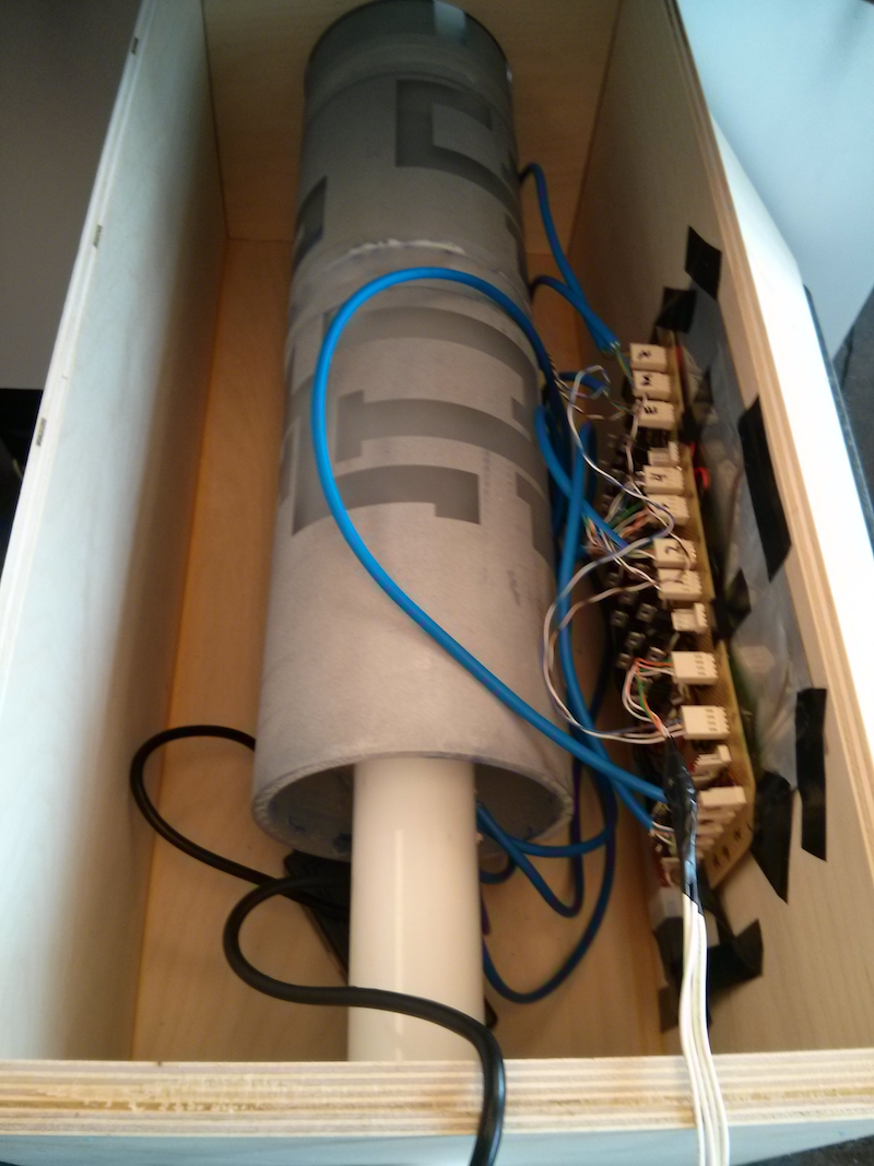
Assembled System
The fully assembled system, including power supply, tucks away nicely into the prototype enclosure, as seen here.

Final Code
The final Arduino code can be seen here. Several elements are commented out, specifically use of insertion sensors and control servos, since those elements were not mechanically implemented into the final prototype.
Future Improvements
Should this device been taken further in development for a 5Wits experience, most of the electronics and control systems would be redesigned to plug into the adventure’s overall control system and to fit the higher grade of lighting and other special effects available to 5Wits. However, the overall logic and core game design elements provide a framework for the adaptation of the system.
